
Piezoelectric vs. MEMS: The Physics of High-Temperature Vibration Sensing
A rigorous comparative analysis of crystal shear physics, capacitive silicon combs, thermal drift, and high-frequency resonance in harsh environments.
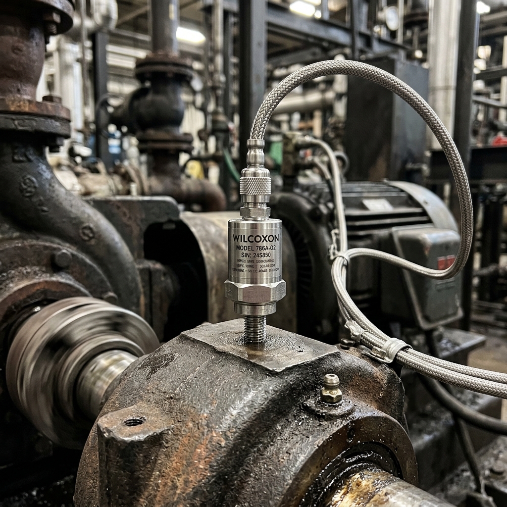
Selecting the correct accelerometer architecture dictates whether predictive maintenance systems perceive impending machine failure or blind operators with thermal noise. Comparing piezoelectric shear crystals against capacitive silicon MEMS establishes the physical operational boundaries for extreme industrial environments.
DAMMAM — Mounted directly onto the cast-alloy casing of a 180-bar boiler feed pump operating in an industrial power and steam cogeneration plant, a vibration accelerometer endures an environmental crucible. Surface temperatures on the pump bearing housing hover continuously at 145 degrees Celsius, radiating thermal energy into the sensor body. Simultaneously, structural high-frequency cavitation hiss and fluid pulsations bombard the sensor base with continuous broadband acceleration forces exceeding twenty-five times the acceleration of gravity. In this punishing operating environment, the internal physics of the sensor determines whether plant reliability algorithms receive an authenticated, high-fidelity kinematic waveform or an aliased, thermally drifted stream of meaningless electrical noise.
In the rapidly expanding condition monitoring marketplace, an intense technical debate pits traditional industrial piezoelectric accelerometers against modern silicon micro-electro-mechanical systems (MEMS) accelerometers. Proponents of MEMS highlight their miniature footprint, surface-mount manufacturing economies of scale, integrated three-axis sensing arrays, and direct digital bus interfaces. Conversely, rotating machinery specialists and instrumentation veterans fiercely defend piezoelectric sensors as the gold standard of heavy industrial reliability.
Resolving this engineering debate requires examining the fundamental physical transducer mechanisms governing both sensor architectures.
An industrial piezoelectric accelerometer operates on the direct piezoelectric effect discovered by Pierre and Jacques Curie in 1880. Inside a hermetically sealed, argon-welded 316L stainless steel housing, a precisely cut ferroelectric ceramic crystal—typically lead zirconate titanate (PZT) or synthetic quartz—is preloaded against an internal seismic mass.
In superior shear-mode designs, the crystal is mounted parallel to the sensing axis, clamped under mechanical compression between a central post and the seismic mass. When mechanical acceleration acts upon the sensor base, the seismic mass exerts a dynamic proportional shear force across the crystal lattice. This mechanical shear displaces ionic charges within the non-centrosymmetric crystal lattice, generating an instantaneous electrical charge q directly proportional to the applied acceleration: q = d * F = d * m * a, where d is the piezoelectric charge coefficient.
Internal Integrated Electronics Piezo-Electric (IEPE) circuitry converts this minute charge into a low-impedance voltage signal transmitted across a simple, noise-immune two-wire coaxial cable.
The primary physical virtue of the piezoelectric shear design is its phenomenal dynamic performance. Piezoelectric sensors deliver continuous, flat frequency response extending from 0.5 Hz to beyond 22,000 Hz, with resonant frequencies typically exceeding 40 kHz. Their dynamic range is massive, comfortably exceeding 120 decibels, enabling them to capture sub-millig micro-vibrations simultaneously with 500 g structural shock pulses without saturation.
Crucially, specialized charge-mode piezoelectric accelerometers operating without internal electronics withstand continuous operating temperatures up to 260 degrees Celsius—and up to 480 degrees Celsius with specialized bismuth titanate crystal chemistry—making them uniquely capable of surviving steam turbine casings and furnace exhaust blowers.
Silicon MEMS accelerometers operate on an entirely different physical principle: variable differential capacitance. Etched into a single chip of monocrystalline silicon using deep reactive-ion etching, a MEMS sensor comprises a central suspended silicon proof-mass supported by microscopic polysilicon flexure springs. Projecting outward from the proof-mass are dozens of interdigitated capacitive fingers that mesh between fixed silicon stator fingers.
When acceleration acts upon the chip, the proof-mass deflects, altering the microscopic gap distance between the moving and fixed fingers, thereby modulating the differential electrical capacitance. On-chip CMOS signal conditioning circuits convert this sub-picofarad capacitance change into an analog voltage or serialized digital bitstream (I2C or SPI).
While MEMS technology has achieved extraordinary advancements, its fundamental physical boundaries must be respected in heavy industrial environments.
First is bandwidth: standard capacitive MEMS sensors exhibit mechanical resonance between 2 kHz and 10 kHz, limiting their reliable linear measurement bandwidth to roughly 1,000 Hz to 4,000 Hz. Attempting to capture high-frequency 102.4 kHz micro-transient bearing shock pulses or execute Hilbert envelope demodulation with standard MEMS devices is physically impossible; the high-frequency impacts fall outside the sensor's response window or drive the silicon proof-mass into non-linear harmonic distortion.
Second is thermal limitation: standard commercial MEMS silicon packaging degrades rapidly at sustained temperatures exceeding 105 degrees Celsius, suffering severe thermal zero-bias drift and sensitivity shift.
The architectural consensus deployed across industrial reliability networks establishes a clear, rigorous demarcation. For balance-of-plant auxiliary equipment—cooling tower fans, general water circulation pumps, conveyor belts, and air handling units operating below 80°C and 1,800 RPM—triaxial silicon MEMS sensors deliver cost-effective, multi-axis diagnostic coverage.
For critical, high-energy turbomachinery trains—multi-stage boiler feed pumps, high-pressure syngas compressors, gas turbines, and severe-service gearboxes—piezoelectric shear-mode accelerometers remain physically non-negotiable. By matching the physical transducer mechanics to the thermodynamic and spectral reality of the machine, reliability engineers ensure that their digital intelligence systems rest upon an unshakeable foundation of authentic physical truth.
The ongoing structural debate in industrial instrumentation pits vintage piezoelectric shear-mode accelerometers against modern silicon Micro-Electro-Mechanical Systems (MEMS) vibration sensors. For over half a century, piezoelectric transducers utilizing synthetic Lead Zirconate Titanate (PZT) or quartz crystals have served as the gold standard for turbomachinery vibration monitoring. When subjected to dynamic acceleration, the seismic mass within the sensor exerts a proportional mechanical force on the piezoelectric element, producing an instantaneous electrical charge displacement: $q = d_{33} cdot F = d_{33} cdot m cdot a$, where $d_{33}$ represents the longitudinal piezoelectric charge coefficient. Internal charge amplifier electronics (IEPE/ICP) convert this high-impedance charge into a low-impedance voltage signal calibrated to standard sensitivities, typically 100 mV/g.
Conversely, silicon capacitive MEMS accelerometers fabricate seismic mass and suspension spring structures directly onto silicon wafers using microscopic photolithographic etching. Acceleration displaces the microscopic proof mass, altering the physical air-gap capacitance between interdigitated stationary and movable comb fingers: $Delta C = epsilon_0 epsilon_r A cdot rac{Delta d}{d_0^2}$. While MEMS technology enables compact triaxial integration, embedded analog-to-digital conversion, and low manufacturing costs, the fundamental physics of microscopic silicon beams introduces severe high-frequency measurement boundaries.
The critical engineering distinction between these two sensor typologies lies in high-frequency mounted resonance, dynamic range, and high-temperature drift. High-end piezoelectric shear accelerometers achieve mounted mechanical resonant frequencies between thirty and fifty-five kilohertz, providing an uncompromising flat linear frequency response ($pm 3$ dB) from 0.5 Hz up to fifteen or twenty kilohertz. This wide bandwidth is indispensable for capturing the high-frequency structural resonance bursts excited by early-stage bearing micro-spalls, high-speed gear mesh impacts, and blade-pass harmonics. Standard silicon MEMS accelerometers, constrained by mechanical silicone damping and internal structural resonances between eight and twelve kilohertz, exhibit severe amplitude attenuation and phase distortion above five kilohertz, rendering them fundamentally blind to early-stage subsurface bearing shear.
Furthermore, the extreme thermal conditions of the Arabian Gulf industrial corridor expose the physical limits of silicon MEMS electronics. In petrochemical facilities where summer ambient temperatures exceed fifty degrees Celsius and uninsulated machinery casing skin temperatures breach one hundred and twenty degrees Celsius, silicon MEMS sensors suffer from severe temperature-coefficient bias drift and piezoresistive saturation. High-temperature piezoelectric sensors, featuring isolated shear-mode geometries and external charge amplifiers, operate continuously in environments up to two hundred and sixty degrees Celsius with temperature coefficients under 0.03% per degree Celsius.
This sensor performance disparity was evaluated in a benchmark trial on a 15,000 RPM high-speed planetary gearbox driving an offshore centrifugal water injection pump in the Arabian Gulf. A triaxial silicon MEMS sensor and an industrial piezoelectric shear accelerometer were mounted on the high-speed pinion bearing housing. The piezoelectric sensor cleanly captured gear mesh frequency harmonics at 8,250 Hz and associated sidebands, detecting tooth micro-spalling forty-two days before failure. The MEMS sensor, overwhelmed by internal capacitive damping above 4.5 kHz, aliased the high-frequency energy into low-frequency ghost harmonics, failing to trigger condition monitoring alerts. For critical, high-speed turbomachinery assets, piezoelectric instrumentation remains the non-negotiable benchmark for physical diagnostic integrity.
Listen to our podcast, Read our newsletter
Join 25,000+ plant reliability and asset health engineers receiving our weekly deep dives.
Subscribe to our weekly systems engineering letter.
Select your engineering discipline to receive calibrated benchmarks and failure modes (ISO 14224).
Related articles
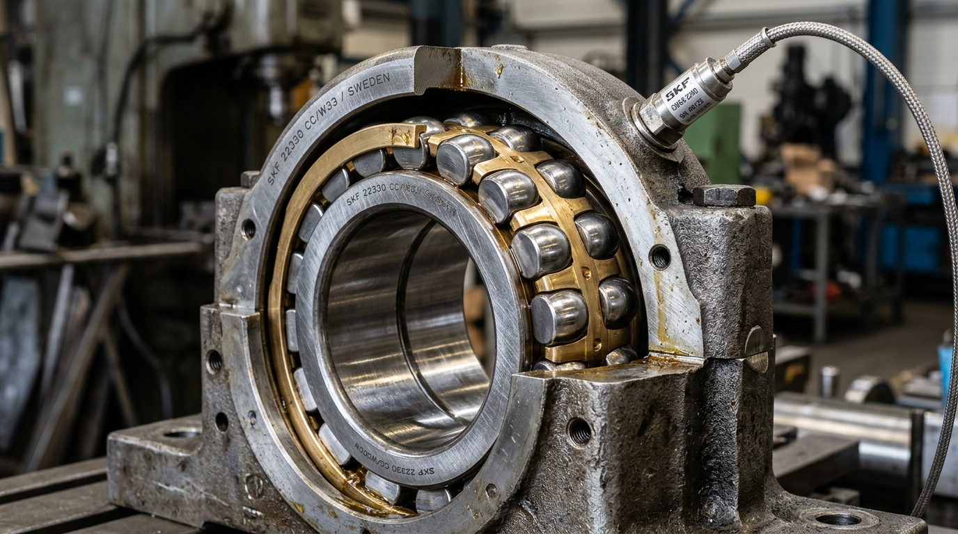
Hilbert Envelope Demodulation: Unmasking Micro-Cracks Before Vibration Alarms Fire
The mathematical physics of amplitude modulation, high-frequency structural resonance, and early bearing fault frequency isolation.
Motor Current Signature Analysis: Non-Invasive Detection of Broken Rotor Bars
The electromagnetic spectral physics of detecting broken rotor bars and dynamic air-gap eccentricity from the motor control center.

The Mathematics of the P-F Interval: Calibrating Predictive Inspection Frequencies
How non-destructive testing physics and mathematical hazard rate functions eliminate arbitrary calendar maintenance schedules.
Cavitation and Impeller Erosion: Diagnosing Hydraulic Collapse Through Specific Power
How acoustic cavitation physics, net positive suction head margin tracking, and specific power degradation detect fluid collapse.
Get started
for free
Try Optruss for as long as you like with full access to autonomous agent workflows and edge telemetry. Deploy across any asset train without proprietary sensor lock-in.